|
A DS2482-800 based 8 channel 1-Wire Master with optional DS1307 RTC. The RPI3 and RPI3a are currently only available fully assembled. The RPI3v1 is only suitable for the early Pi models with a 26 pin GPIO header. For all models with the 40 pin GPIO header (A+/B+/Zero/Zero2/2/3/4/5) you'll need an RPI3v2 They're electrically identical, just on different PCBs to suit the different Pi Form Factors. They are available to purchase in our online store. 
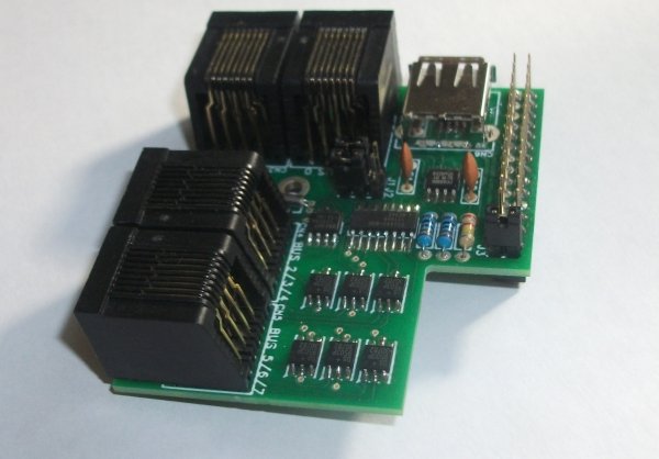
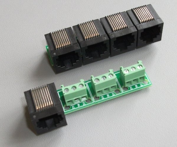
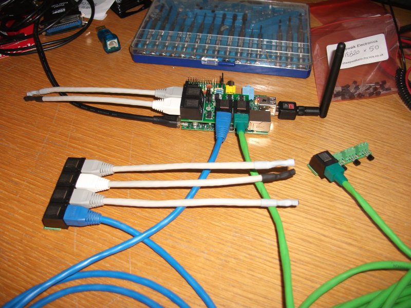
(click on any photo to see a larger version) The photos above show an RPI3v1 This is a temporary page to give a quick guide on the RPI3. It will be replaced by better documentation shortly. Please click here for an image of an RPI3 and two RPI3a modules. It shows an RPI3 on a Raspberry Pi and also both versions of the RPI3a connected to it with the green and blue cables. The sensors shown are simply SWE0 sensors with very short cables used for testing. It is very important if you have an RPI3 with the RTC option that you do not connect the RPI3 to your Raspbery Pi without inserting a battery in the holder on the underside. Doing so could potentially damage the RTC IC on your RPI3. You will need a 3V CR1632 button cell. Due to postage restrictions we are not able to supply a battery so you will have to source your own. The battery is to be inserted with the positive side upwards allowing you to read the writing on the top of the battery. If you have an early Pi and an RPI3 with the RTC option then the battery holder on the RPI3 and the P2 header on your Pi will clash. If you want it to work you'll have to remove/bend/alter the header. On the later Pis this header has nothing soldered into it so there is no issue. If you have the non-RTC RPI3 then there is also no issue as the battery holder is not present. If you have a later Pi then the supplied nylon screw assembly can be used to secure the RPI3 to your Pi. It should be assembled with one of the thin washers each side of each PCB (the Pi and the RPI3) with the large spacer in the middle of the whole lot, so from bottom to top the order goes screw, washer, Pi, washer, spacer, washer, RPI3, washer, nut. Do not overtighen this or you will either snap the screw, damage your Pi, or both. The software setup for the 1-Wire part of the RPI3 is essentially the same as for the RPI2 but you will see 8 1-Wire busses instead of 1, numbered bus.0 up to bus.7. See the RPI2 page for more details of this. To configure the RTC part this post on the Raspbery Pi forum seems to cover most of what you need to do, but the line starting "echo pcf8563" should have the "pcf8563" replaced by "ds1307". The USB socket on the RPI3 is a power input socket and is not normally needed, the RPI3 will get its 5V supply from the Raspberry Pi. If you will be using power hungry 1-Wire devices and wish to provide your RPI3 with its own power supply then remove jumper J3 (to disconnect the RPI3s 5V line from the 5V line on your Raspberry Pi) and connect a regulated 5V supply to the USB socket on the RPI3. The RJ45 sockets along the left side of the PCB (above the power connector and SD card) have one bus on each (busses 0 and 1) and are wired to the same standard as the RPI2 and all our other modules to allow easy connection via Cat5 cable. Four pins are connected, pins 1 and 2 (GND and +5V), and pins 4 and 5 (1-Wire Data and Ground). The RJ45 sockets along the bottom of the PCB (above the HDMI socket) have three busses on each (busses 2,3,4 and 5,6,7) and are wired as follows. Pins 1 and 2 are GND and +5V. Pins 4 and 5 are data and ground for the first 1-Wire bus (the blue cable pair on normal Cat5). Pins 6 and 3 are data and ground for the second 1-Wire bus (the green cable pair on normal Cat5). Pins 8 and 7 are data and ground for the third 1-Wire bus (the brown cable pair on normal Cat5). The easiest (well cheapest at least) way to connect to these is cut one end off a length of Cat5 cable and use the blue, green and brown pairs as your three busses. Alternatively if you want to convert these sockets to normally wired RJ45 sockets or screw terminals then the RPI3a module is what you need. Simply connect the RPI3 to the first RJ45 on the RPI3a and you then get either three normally wired RJ45 sockets or three sets of 3 pin screw terminals. I hope that all makes sense. Questions are welcome via email or on Facebook. |